
 Esperanto
 Shqiptare
 Euskara
 Zulu
Zulu
 Latinus
 Cymraeg
 தமிழ்
தமிழ்
 Slovak
 Slovak
 Afrikaans

-
-
About Us
-
Service
-
News

News Center
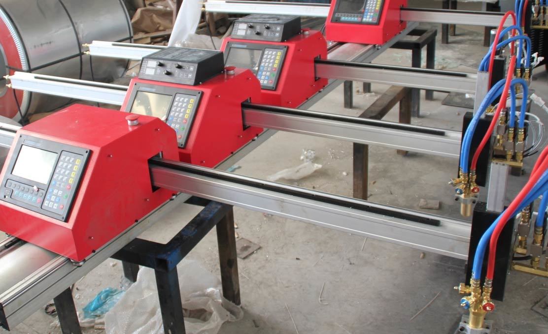
What is the Plasma Cutting Process?
Plasma cutting is a widely used thermal cutting process capable of slicing through any electrically conductive material. Utilizing a high-velocity jet of ionized gas (plasma), it offers a powerful combination of speed, versatility, and the ability to cut thick metals, making it a staple in many industries. Understanding the fundamentals of how it works, the gases involved, power requirements, and proper maintenance is key to leveraging its full potential.
How Does Plasma Cutting Work?
The plasma cutting process relies on creating an electrical channel of superheated, ionized gas – the plasma – which is forced through a constricting nozzle onto the workpiece. Here’s a breakdown of the steps:
- Gas Flow: An inert or active gas (like compressed air, nitrogen, oxygen, or argon mixes) is supplied to the plasma torch.
- Arc Initiation: A high-voltage, low-current pilot arc is typically established between the electrode (inside the torch) and the nozzle tip. This initial arc ionizes a small portion of the flowing gas.
- Plasma Jet Formation: As the torch approaches the conductive workpiece, the main cutting arc forms between the electrode and the workpiece, transferring significantly more electrical energy. This intense energy rapidly heats the flowing gas to extreme temperatures (up to 20,000°C / 36,000°F or more), causing it to ionize and become plasma.
- Melting and Ejection: The plasma jet, constricted and accelerated by the nozzle orifice, strikes the workpiece with high thermal energy and velocity. This melts the localized area of the metal.
- Severance: The high velocity of the plasma gas stream physically blows the molten metal away from the cut area, creating the separation or kerf. The torch moves along the desired path, continuously melting and ejecting material to make the cut.
Plasma Gases and Their Roles
The choice of plasma gas (and sometimes a secondary shield gas) significantly impacts cut quality, speed, and consumable life, especially depending on the material being cut:
-
Compressed Air:
- Process: Often used as both the plasma gas and shield gas. Readily available and cost-effective.
- Applications: Good versatility for cutting mild steel, stainless steel, and aluminum, especially in handheld applications or where edge nitriding (hardening) on stainless isn't a major concern.
- Considerations: Requires clean, dry air (oil and moisture severely impact cut quality and consumable life). Can cause oxidation and nitriding on the cut edge.
-
Oxygen (O₂):
- Process: Primarily used as the plasma gas for cutting mild steel. Often paired with air or nitrogen as a shield gas.
- Applications: Provides the best speed and edge quality on carbon steels due to an exothermic reaction (the oxygen reacts with the steel, generating additional heat). Results in sharp, square edges with minimal dross.
- Considerations: Requires specific oxygen-rated torches and consumables. Consumable life can be shorter compared to nitrogen cutting. Not suitable for stainless steel or aluminum.
-
Nitrogen (N₂):
- Process: Excellent choice as a plasma gas for cutting stainless steel and aluminum. Can also be used for mild steel. Often paired with CO₂, air, or water injection/shielding.
- Applications: Provides excellent edge quality and minimizes oxidation on stainless steel and non-ferrous metals. Good balance of cut quality and consumable life.
- Considerations: Generally results in slightly slower cutting speeds on mild steel compared to oxygen.
-
Argon/Hydrogen Mixes (e.g., H35 - 35% Hydrogen, 65% Argon):
- Process: Typically used as the plasma gas for cutting thicker stainless steel and aluminum (often > 0.5 inches / 12mm). Nitrogen is commonly used as the shield gas.
- Applications: Delivers maximum cutting capability and excellent edge quality on thick non-ferrous materials due to the high thermal conductivity of hydrogen. Produces very clean, smooth cuts.
- Considerations: More expensive gas mixture. Requires specialized water-injection torches or specific equipment designed for these gases due to the high heat.
Plasma Power Source Sizing (Amperage)
The plasma power supply's output, measured in Amperes (Amps), directly determines the system's cutting capacity (material thickness). Choosing the right size is crucial for performance and efficiency:
- Low Power (approx. 30-60 Amps): Suitable for cutting thinner sheet metals, typically up to around 1/2 inch (12mm). Ideal for HVAC, automotive bodywork, and light fabrication.
- Medium Power (approx. 60-130 Amps): The workhorse range for general fabrication, capable of cutting materials typically up to 1 inch (25mm) or slightly more. Common in fabrication shops, manufacturing, and maintenance.
- High Power (approx. 130 Amps and above, up to 400A+): Designed for heavy plate cutting, often found in industrial settings like shipbuilding, bridge construction, heavy equipment manufacturing, and service centers. These systems can cut materials several inches thick.
Note: Always refer to the manufacturer's specifications for precise cutting capacities at different amperages for various materials. Duty cycle (the percentage of time the machine can operate at a given output within a 10-minute period) is also a critical factor for production environments.
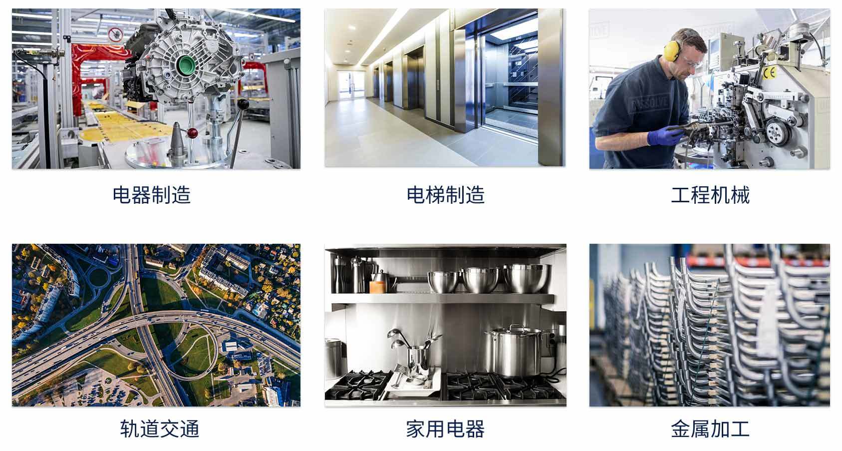
Industries Utilizing Plasma Cutting
Plasma cutting's versatility makes it valuable across numerous sectors:
- General Metal Fabrication: Cutting parts for structures, machinery, and custom projects.
- Construction: Cutting beams, plates, and pipes on-site or in fabrication.
- Automotive Repair & Manufacturing: Chassis work, exhaust systems, custom vehicle builds.
- Shipbuilding and Repair: Cutting hull plates, frames, and other structural components.
- Mining and Heavy Equipment: Manufacturing and repair of durable machinery parts.
- Industrial Maintenance & Repair: Quickly cutting seized bolts, replacing worn sections, plant modifications.
- Salvage and Demolition: Rapidly breaking down metal structures and vehicles.
- Artistic Metalwork: Creating intricate designs and sculptures.
Essential Maintenance for Plasma Cutter Longevity
Consistent maintenance is vital for ensuring reliable performance, optimal cut quality, and extending the lifespan of your plasma cutting equipment:
-
Daily / Before Each Use:
- Inspect Consumables: Check the electrode (for pitting beyond limits), nozzle (for orifice wear/damage), shield cap (for spatter/damage), and swirl ring (for cracks/blockage). Replace worn parts immediately – running with worn consumables drastically reduces cut quality and can damage the torch.
- Check Torch Body: Inspect for any physical damage or cracks.
- Verify Gas/Coolant Flow: Ensure proper pressure and flow rates. Listen for leaks. Check coolant levels (if applicable).
-
Weekly / Periodic:
- Clean Torch Body and Leads: Wipe down components to remove dust and grime.
- Inspect Cables and Hoses: Look for cuts, abrasions, kinks, or burn marks. Ensure secure connections.
- Check/Clean/Replace Air Filters: Crucial if using compressed air. Ensure moisture traps are drained regularly. Dirty or wet air is detrimental.
- Check Coolant System (if applicable): Verify coolant conductivity/condition and change according to manufacturer recommendations. Clean filters.
-
General Practices:
- Keep the Area Clean: Metal dust can interfere with electronics and moving parts.
- Ensure Good Ground Connection: A poor ground causes starting issues and inconsistent cutting.
- Follow Manufacturer Guidelines: Adhere to the specific maintenance schedule and procedures outlined in your equipment manual.
By diligently performing these maintenance tasks, you can significantly minimize downtime, reduce operating costs, ensure consistent cutting performance, and maximize the return on your plasma cutting investment.